 |
 |
 |
 |

|


|
|
|
|
|
|
#1
|
|||
|
|||
|
Dual fan wiring help
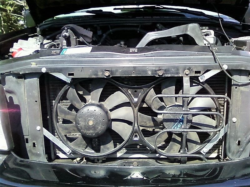
I have one of those dual fan setups, where one fan is powered and the other fan is driven off a belt, so there's only two wires to deal with. I'm trying to use this fan setup on a GMC Sonoma V8 conversion truck I have, but have not been able to get these fans to come on. I have a 30A relay with a 20A inline fuse, trying to go thru a switch in the cab. I for the life of me cannot get these fans to come on.
There is a black wire and a brown wire coming off the one fan, so I'm assuming black is ground and brown is power? On the relay, the fused wire goes to battery positive, another wire goes to fan power (brown wire?), and the other wire goes to the switch. When I toggle the switch to ON, the LED lights up so I know the switch is getting power, but the fans don't come on. I have no automotive electrical knowledge, but I'm thinking the problem is with the fan. Am I missing a component that's supposed to make these fans come on? All I want them to do is turn on via the switch in the cab, no variable speed, no temp control, etc., so I thought just wiring them up thru a relay would make them come on? If I can't get these dual MBZ fans to work, I'm seriously thinking of just getting two separate 11" fans, running them thru dual relays, to the switch, and be done with it. Worst case scenario is I have a switch for each fan, but I can deal with that. So why won't these dual MBZ fans come on?! 
Last edited by socal1200r; 10-21-2016 at 06:48 PM. |
|
#2
|
|||
|
|||
|
Germans use brown as ground.
|
|
#3
|
|||
|
|||
|
Quote:
Using jumpers/test leads, connect the fan directly to battery: brown>neg., black>pos. Does the fan run? 2) Make a drawing of the wiring: fan, relay, battery, & switch. Scan & upload as a thumbnail to this thread. |
|
#4
|
|||
|
|||
|
Seriously, BROWN is ground?! Okay, I've got some rewiring to do then, before throwing in the towel. Also, since the fan shroud is metal, is it supposed to have it's own ground as well?
I'm going to feel like a total idiot if switching the wires makes everything work, lol... |
|
#5
|
|||
|
|||
|
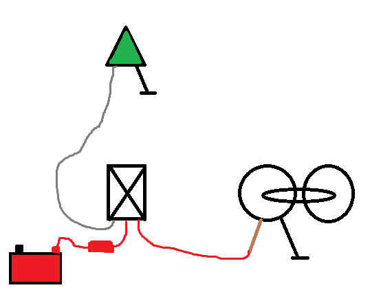
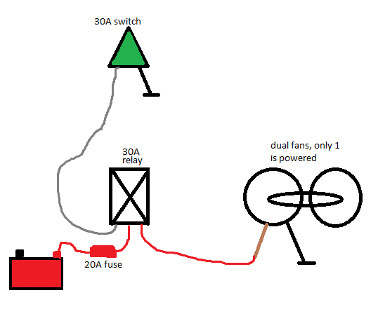
You'll have to excuse my limited Paint skills, but this is a diagram of how I have these fans wired up:
 Brown wire off the fan to relay power, black to ground. I now know that these have to be reversed. Other relay red, with an inline 20A fuse, to battery positive. Gray off relay to switch. Black off switch to ground. The switch is working fine, the LED goes on and off when I toggle the switch back and forth. So if I switch the brown and black wires coming off the fan, they should turn on, even without the engine running or key turned on? Or does the engine have to be running because of the initial load when the fans start up? |
|
#6
|
|||
|
|||
|
Quote:
As far as I know, the only thing wrong in the diagram is the brown and black wires coming off the fan have to be switched, since brown is ground and black is power. When I go to test them again, I'll use some jumper wires and ground the metal fan shroud as well, just in case... 
|
|
#7
|
|||
|
|||
|
Hopefully, my two previous posts with the wiring diagram will finally show up, so I'll just keep writing...(apparently, my previous posts had a picture or weblink embedded, and they have to be approved...whatever...)
Disconnected the wires at the fan and ran them directly to the battery, brown to ground and black to positive, and viola, the fans came on, and those puppies move a serious amount of air! However, the jumper wire got SO hot so quickly I had to disconnect it asap. So that's telling me those fans are pulling a lot of juice. I used the multimeter to check the ground wire I had going to the fan, and it's good. The connection of the fused line off the relay to the battery had a good connection at the battery. However, when I tested the end of the wire coming off the relay to the fan power, it didn't register anything. I tested the switch per the diagram, running the ground off the switch to the ground wire for the fan, and the switch worked (LED light came on in the "ON" position, went off in the "OFF" position). However, the switch, as wired in the diagram, would not turn the fans on. I checked the 20A inline fuse from the relay to the battery, and it was fine. I went to Pep Boys and spent some time in their electrical section. Found a 40A relay, a relay connection, inline fuse holder for a blade fuse, some 14g wire, and some 14g wire connectors. One thing different about this 40A relay is it has a ground wire, where the 30A relay I'm using now doesn't. I'm planning on putting a 30A fuse into the new line, so maybe that will make a difference? I'm going to try and wire up these new components tomorrow morning, and hopefully it'll work. The fans work when wired directly to the battery, and the switch works, so it has to be the relay, right?! Last edited by socal1200r; 10-22-2016 at 06:50 PM. |
|
#8
|
|||
|
|||
|
Dr. Watson would concur.
|
|
#9
|
|||
|
|||
|
Attempted to get these fans to work again today, no joy. There are two relay "parts", one is the relay itself, which has a diagram, and the other is the "socket", that has wires already plumbed to it. So I attached the "socket" to the "relay", and went about wiring it up according to the diagram on the "socket". I thought it was odd that the white wire was ground and the black wire went to a switch, but off I went. Connected the blue wire up to battery positive with an inline fuse, and the yellow wire went down to fan positive. When I jumped the fan positive directly to the battery, the fans came on, which tells me there's also a good ground down at the fans. When I jump the switch directly to the battery, it lights up like it's supposed to, so I know the switch works.
So of course when I got everything wired and toggled the switch, the fans didn't come on. I tested the "socket" ground against the switch and battery positive, and the switch worked, so that ground is good. I tested "socket" power up at the battery by disconnecting the fused wire and jumping the switch there, and the switch worked, so I know the power connection is good. So it would appear that the power and ground wires off the "socket" are good, that leaves the switch and output wires. I already know the switch doesn't work when it's wired up to the switch wire, and without that working, I can't test the output wire, i.e. disconnect the output wire to the fan, flip the switch to "ON", then use a multimeter to see if there's voltage coming off the output wire. Now what's interesting is the wiring diagrams on the relay and the socket are different. The output and power are the same, but ground and switch are reversed. I'm going to defer to the diagram on the relay as being the correct one, because that one says black is ground and white is for the switch, which makes more sense. I am SO frustrated by this whole ordeal I'm ready to go to the range and burn thru a couple of boxes of bullets. This is freaking ridiculous! I'm at wits end now trying to get these fans to come on. What should be something fairly simple is turning out to be my worst nightmare. I mean, how hard can it be to wire these damn things up, when I know the fans work and the switch works when you jump them directly to the battery. It's got to be the freaking relay wiring that's making me crazy. So the next step I'm thinking of doing is unplugging the "socket", and wiring it up directly off the relay. There's only four terminals, so how badly could I screw that up?! I was so frustrated I put everything away and went for a motorcycle ride, to help calm me down. This is so freaking ridiculous, I'm besides myself. Oh, and to further complicate things, I decided to jump the wires on the 14" Derale fan I took off, and guess what? Yup, I couldn't get that fan to come on at all, whereas the dual MBZ fans would come on with a direct jump. WTF, over?! This is why automotive electrics make me so freaking mad. What should be something simple is going to take a rocket scientist to figure out... |
|
#10
|
|||
|
|||
|
be careful on these fans and wiring, wiring them as on/off for full power through a 40A relay can cause the relay to weld itself on as the main fan sucks a ton of juice when starting.
MB drive these fans through a PWM control module to ease the amp draw. You might want to use one of the standalone fan control units that have a probe which is stuck into the radiator fins to ease the fan on and off. I installed a couple of fans in an old chevy truck and used three relays to run the fans in 2 speeds. the circuit simply makes the fans run in series or parallel.
__________________
2012 BMW X5 (Beef + Granite suspension model) 1995 E300D - The original humming machine (consumed by Flood 2017) 2000 E320 - The evolution (consumed by flood 2017) |
|
#11
|
|||
|
|||
|
I emailed a friend of mine back in So Cal about this, and he gave me another option, one I didn't think about. He said from what I told him about the wiring diagram for the relay and the relay socket, they're both wrong. He then told me which wire should be going to which function off each terminal on the relay, and they didn't match the diagrams on the parts boxes at all!
So after work today, I'm going to disconnect all the wires coming off the relay socket, look at the relay terminal numbers, find the associated wire, then route it accordingly, ignoring the box-supplied diagram. Maybe that will get this thing to work... Guess I could've made a faulty assumption in thinking that the wiring diagrams on the back of the boxes were actually correct... |
|
#12
|
|||
|
|||
|
Okay, this thing is kicking my ass. I unplugged the relay "socket" so I can look at the terminal numbers on the relay itself. I wrote down which color wires off the socket went to which terminals on the relay itself, to make wiring things up a little easier for me. But I realize that saying which terminals went to which functions is a better indicator of what I did, instead of wire color, so here goes.
Attempt 1: 30: output to fan 85: to 30A switch with LED indicator 86: to ground 87: to battery positive (30A fused line) Result: nothing, switch did NOT turn the fans on Attempt 2: 30: output to fan 85: to battery positive (30A fused line) 86: to ground 87: to 30A switch with LED indicator Result: same as 1 Attempt 3: this is the wiring diagram on the relay "socket" 30: output to fan 85: to ground 86: to 30A switch with LED indicator 87: to battery positive (30A fused line) Result: same as 1 Attempt 4: this is the wiring diagram on the relay itself 30: to battery positive (30A fused line) 85: to ground 86: to 30A switch with LED indicator 87: output to fan Result: same as 1 I then installed a fused line with a 25A blade fuse for the switch, and repeated all four diagrams above. Then I removed the relay socket and ran wires directly off the relay terminals, and got the exact same results, switch did not turn the fans on. Then using black as ground, I attempted every variation of wiring combinations I could think of with the three remaining wires, and got nothing. It's a good thing I'm taking medication, because I'm ready to rip these fans out of the truck and smash them into a million pieces... Is it possible that the relay itself is bad? How can I test that (my test light doesn't work, but I do have a multimeter)? After every wiring attempt, I then jumped the fans and the switch to the battery, and they both worked, so it's not those components. Again, by process of elimination, it has to be the relay? |
|
#13
|
|||
|
|||
|
Don't they teach electrical shop in school these days? Both the coil and contact need power. Here's the circuit. If you really want it to be perfect, 87A should also be grounded, but it can usually be left open as shown without any obvious problem.
|
|
#14
|
|||
|
|||
|
So according to your diagram, there's no ground coming off the relay, and those two terminals need to be spliced together to the battery? I'll certainly give that a try tomorrow...
|
|
#15
|
|||
|
|||
|
Mx, socal:
The circuit drawn by Mx is functionally correct; in most circuits 30 & 87 would be interchanged, so that 30 is connected to the power source, and 87 to the load. If 30 & 87 are switched on Mx's drawing, it will be conventional. So: 30 & 85 to 12V+ 87 to fan motor 86 to switch Caution: 87a should not be grounded. It is connected to 30 when the relay is de-energized, and hence is hot. |
 |
| Bookmarks |
|
|