

|
|
|
|
|
|
#1
 04-25-2011, 10:03 PM
|
|||
|
|||
|
I have a 1994 E320 wagon (M104.992 engine) 181k miles, that had a dead transmission and serious oil leaks. After I pulled the motor rebuilt the trans and redid all seals I realized I forgot to note the direction off the vacuum system. I was able to find a couple diagrams online to give me a general idea of what needed to be done and thought I had it right.
I was know I was wrong because I found a large black vacuum tube when I cleaned out the garage recently and rubber connector as in the pic below (pulled this off google) that connects to the throttle body. This must go to something that need lots of vacuum. 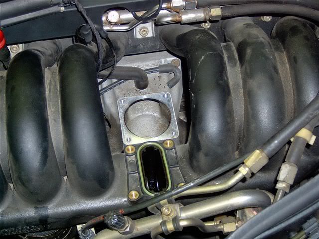 This is the current diagram of how my vacuum system is routed: 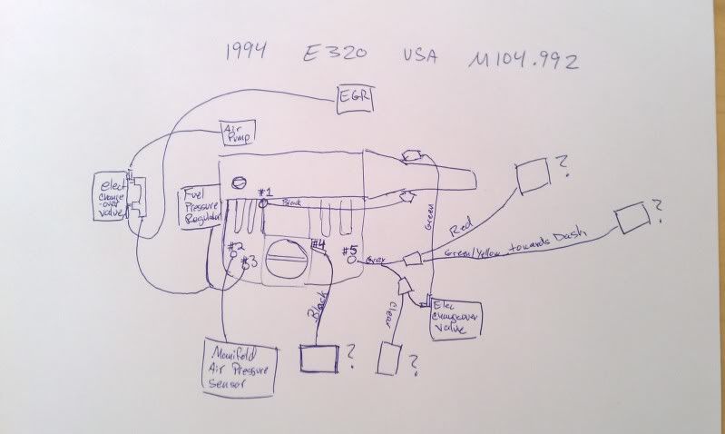 #1 connects to Transmission Vacuum Modulator #2 to MAP sensor #3 Electric Changeover Valve and Fuel Pressure Regulator #4 currently goes to the wrong place - connected to a sensor on black plastic center of intake housing, and I think I am adding vacuum to something that shouldn't have any #5 goes to a Y and each branch splits to two directions each with a check valve(?) in each junction I know I have #4 wrong for sure, but this means I must have #2 and #3 off as well. I may have the lines to the EGR and the Air Pump mixed up as well. Symptoms; When car is first started there is a 30-60 seconds of what sounds like a large exhaust leak (louder shushing/hissing sound). I am burning a bit of oil (not leaking as there are just a couple small juicy spots on the motor and no drips (this could be unrelated though there was no scoring on cylinder walls and cross hatching was in ok shape). Any help would be great. Also if there are any W124 M104 owners in the LA area that wouldn't mind if I took a look at their engine bay that could help me solve this too. Thanks! 

|
|
#2
04-25-2011, 10:15 PM
|
||||
|
||||
|
Is that the crankcase-vent tube/elbow?
__________________
 Gone to the dark side - Jeff
|
|
#3
04-25-2011, 11:15 PM
|
|||
|
|||
|
Quote:
I received some pdf links in a PM (thanks AD) that show this should go to the "regeneration switchover valve" according to one doc, or to the "Purge control valve" in another doc...both labeled Y58/1 Trying to figure out where it is located in the engine bay.
|
|
#4
04-25-2011, 11:29 PM
|
||||
|
||||
|
Left fender.
__________________
Gone to the dark side - Jeff
|
|
#5
04-25-2011, 11:38 PM
|
|||
|
|||
|
was PM'ed a pic too

|
|
#6
04-26-2011, 09:21 AM
|
|||
|
|||
|
Here is the pictures.
pic 1 and 2.. that's where the u ( in your first picture) connected to Pic 3 ( in red circle ) it's Y connector, one connected to fuel pressure regulator (in pic 4.) the other go to pic 5. Pic 5. the right red tube go to EGR. Picture's taken from 93 300E (m104 3.2L)
|
|
#7
04-26-2011, 02:44 PM
|
|||
|
|||
|
Quote:
|
 |
| Bookmarks |
|
|


 Linear Mode


