

|
|
|
|
|
|
|||||||
 |
|
|
LinkBack | Thread Tools | Display Modes |
|
#1
 06-09-2013, 06:53 AM
|
||||
|
||||
|
More than you are likely to ever want to know about OM61X piston vacuum pumps
G'day folks,
I thought I'd share my recent experiences with a piston vacuum pump – as well as some of my stir crazy busyness in this past long long winter when I've spent more time stuck indoors than ever before. In the beginning I planned to just do a simple DIY for replacing the bearings on the cam follower, but it got out of hand. Now there are several DIYs in one. Today I can present to you
I'm also figuring out some more (silly?) engineering stuff that I'll be adding later on when I get bored or when the next endless winter kicks in. So this thread is a work in progress. All sounds a bit weird eh? If you're interested read on! But I warn you now this is a big 'un. This all started when I saw an on-line bargain – a vacuum pump that had been fitted to a (W123) 200D. I struck a deal and it cost me €27 delivered. It came in a slightly damaged state with two screws broken off of the cover – but hey – you can't look a gift horse in its mouth. In the mucky climate in which I live all of these screws corrode and get stuck; it was a shame that the screws were broken but I reckoned I could fix it. 
__________________
1992 W201 190E 1.8 171,000 km - Daily driver 1981 W123 300D ~ 100,000 miles / 160,000 km - project car stripped to the bone 1965 Land Rover Series 2a Station Wagon CIS recovery therapy! 1961 Volvo PV544 Bare metal rat rod-ish thing I'm here to chat about cars and to help others - I'm not here "to always be right" like an internet warrior  Don't leave that there - I'll take it to bits! Last edited by Stretch; 06-10-2013 at 10:01 AM. Reason: Added picture 
|
|
#2
06-09-2013, 06:56 AM
|
||||
|
||||
|
Vacuum pumps are interesting things! ...
...When you're stuck inside in a mucky winter wishing you could get outside and do some welding
Vacuum was widely used by Mercedes to do many things that on the whole are now more commonly done by electric solutions. On an OM61X powered W123 it is used to assist braking, change the height of your headlight beams, help shift your automatic transmission, stop your engine and operate the central locking system. The vacuum pump is mounted on the front of the OM61X engines. The piston vacuum pump consists of a piston that sucks air from the vacuum system and pushes it into the engine's crankcase. Non return valves help to maintain the vacuum created by the piston. 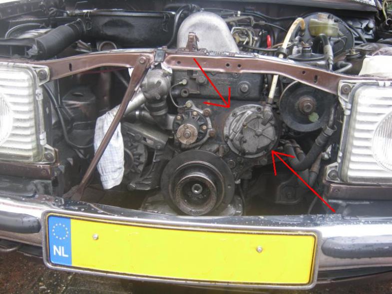 The piston is propelled along its stroke by a lever with a wheel on it that rides over a “roller coaster” cam on the front face of the timing device. Two springs are used to push the lever and the wheel onto the roller coaster cam surface on the timing device.  As the timing device is connected to the injector pump (IP) via an intermediate shaft, it might seem as though the vacuum pump is driven at half of the speed at which the engine / crank is rotating 1. However, for each full rotation of the timing device the piston in the vacuum pump travels its full length (or stroke) four times.  So the vacuum pump piston travels at the same frequency as the pistons in the engine. This means that that little piston in the vacuum pump needs a lot of oil to keep it happy (as do the pistons in the engine). Oil is supplied to this area of the engine by a dripping effect from the top of the cylinder head after it has been sprayed over the valve train. Oil in the vacuum system, however, is unwanted; so an oil check valve is positioned on the input of the vacuum pump.   One of the interesting things about vacuum pumps that I've read about previously is the theory that as the piston in the vacuum pump matches the frequency of the engine piston motion; the vacuum pump piston is deigned to park itself once sufficient vacuum has been made. It has been suggested that the suction of the vacuum produced by the pump is enough to pull the piston and the lever and the wheel away from the roller coaster cam surface on the timing device. This seems to be fantastically clever – but does it actually happen? I'm going to try and attempt to answer this in a little high school science experiment presented towards the end of this thread. Another interesting or rather horrifying aspect of the OM61X piston vacuum pumps is their apparent willingness to shed their parts into the engine's timing chain causing serious damage. These vacuum pumps have a bad name. Truth be told the fault isn't entirely the vacuum pump's. The bushings that hold the timing device and the intermediate shaft in position wear. This is due to the cyclical pounding of the vacuum pump piston assembly being forced on to the roller coaster cam surface of the timing device. If the intermediate shaft bushings wear too much then the intermediate shaft and the timing device shuttles back and forth in time with the vacuum pump piston motion. This is a bit of a design problem. Here are some links to other threads on the forum that might be of interest VACUUM PUMP FAILURE! Are you neglecting yours?? Will these bearings work for a vacuum pump? Vacuum Pump Rebuild Thread OM617 Vacuum pumps http://www.mbca.org/forum/pierburg-vacuum-pump-rebuild 1This is because all OM61X engines are four stroke diesels. The valve train and the injector pump are timed to run at half of the speed of the crank. For more information about four stroke engines see Four-stroke engine - Wikipedia, the free encyclopedia
__________________
1992 W201 190E 1.8 171,000 km - Daily driver 1981 W123 300D ~ 100,000 miles / 160,000 km - project car stripped to the bone 1965 Land Rover Series 2a Station Wagon CIS recovery therapy! 1961 Volvo PV544 Bare metal rat rod-ish thing I'm here to chat about cars and to help others - I'm not here "to always be right" like an internet warrior Don't leave that there - I'll take it to bits! Last edited by Stretch; 06-10-2013 at 09:34 AM. Reason: Added pictures
|
|
#3
06-09-2013, 06:57 AM
|
||||
|
||||
|
Removing an OM61X piston vacuum pump
To remove a vacuum pump from your OM61X engine it is pretty straight forward – you undo vacuum line input and then the Allen head bolts that hold it onto the block.
It is advisable to push hard against the vacuum pump when you remove the last two bolts because there is a possibility that the cam follower on the piston pump is at the highest point on the roller coaster cam (timing device). The force of the spring in the piston pump is strong enough (at least 400N) to help you damage the last threads on the bolts as you remove them if you are not careful.
__________________
1992 W201 190E 1.8 171,000 km - Daily driver 1981 W123 300D ~ 100,000 miles / 160,000 km - project car stripped to the bone 1965 Land Rover Series 2a Station Wagon CIS recovery therapy! 1961 Volvo PV544 Bare metal rat rod-ish thing I'm here to chat about cars and to help others - I'm not here "to always be right" like an internet warrior Don't leave that there - I'll take it to bits! Last edited by Stretch; 06-10-2013 at 09:38 AM.
|
|
#4
06-09-2013, 06:58 AM
|
||||
|
||||
|
Rebuilding an OM61X piston vacuum pump taking it to bits
The process of replacing the cam follower (P/N 000 586 08 43) in the pump is described in chapter 43-635 in the FSM. Whilst chapter 43-628 covers the procedure for resealing the piston and replacing the valves.
To replace the cam follower you need to go through most of the process of replacing the valves. The first step is to remove the cover. In many parts of the world it seems that most people just get a flat blade screw driver and unscrew the screws. No such luck in Northern Europe. All of the covers I've seen have corroded screws. If you are not careful you will burr the edges of the slots on the screws – or as you can see in the picture above (showing the pump I bought) you can snap off the heads. To get those corroded screws out I have tried
If you are trying to remove a corroded screw with any of these methods you are probably wasting your time. If you ever get these screws out you'll see that the corrosion goes about 3 to 4 mm into the hole – no penetrating oil or heat will help and scratching away the corrosion at the surface is well just scratching the surface...   The only thing that I have found that works is hammer and impact driver.  Notes about impact drivers – if you get it working the wrong way you could damage stuff. If you haven't used an impact driver before you need to have faith in the arrows marked on the side of the cheap imported thing you've bought that comes in a little metal red box. You need to twist and click the driver to the arrow if you want it to undo (or do up) in that direction. Place the vacuum pump on a strong bit of wood (such as a bit of OSB). You can then select a good fitting bit and position the impact driver in the screw. Next hold the impact driver with one hand whack the top of it with a heavy hammer. If you need to make another blow make sure that the impact driver is still in the correct position (check arrow) before you hit it again. Most of you lucky buggers in decent climates will have just removed the cover – you'll be able to see something like this. 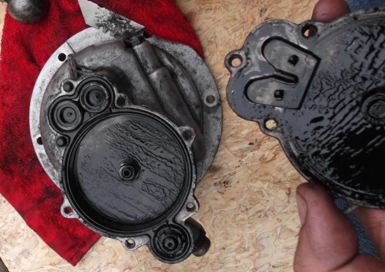 Note even the cover was corroded to the pump body on the pump I bought – I used a Stanley knife blade to split the two parts. If you choose to do this – be very careful. Be careful that you don't stab yourself. Be careful that you don't put too much pressure when angling the cover away from the pump body. It is easy to snap off a part of the cover and end up with something like this.  If this happens you'll then be starting threads like this => http://www.peachparts.com/shopforum/mercedes-used-parts-sale-wanted/338138-wtb-cap-om61x-piston-vacuum-pump.html If you have broken the heads off of the screws and have threaded portions randomly sticking out of the pump body then you are better off stripping down the whole pump and following the tips I'll give on fixing these problems later on in this thread. Remove the non return valves and the funny shaped rubber O ring.  To remove the cam follower you need to undo the 11mm hex head nut that holds the piston in place. The FSM says you should use their special tool to do this job (P/N 115 589 14 21 00) amb  Other people have reported that you can easily replicate this special tool (see http://www.vegmyride.ca/index.php?pr=Rebuilding_Mercedes_Vacuum_Pump). I reckon the only reason why this special tool is used is to stop damage to the last few bits of thread on the push rod as the retaining nut is being undone. This could happen because the piston is held in a state of pretension by the two piston return springs. My solution was to use a hydraulic press to push the cam follower into the pump body and then to undo the nut – total over kill.   I realise that for some readers the use of hydraulic press brings a sinking feeling to their hearts! It poses the question “Where am I going to find one of those?” Well the easiest solution to the problem is to mount the vacuum pump back onto the engine and then undo the nut holding the piston in place. You can also achieve the same with pieces of wood and a G-clamp if you don't have an engine to hand or you've got the timing device removed from the engine for some other reason. When pressure is released from the cam follower the return springs pop out most of the way. (If doing the re-mounting on the engine trick – look out for those threads again – see above for the removal of the pump tip)     To remove the cam follower arm and the springs you can now undo the screw on the outside of the pump body.   And now you can slide the pin away from the cantilever arm mounting point. You do not need to use anything particularly aggressive here – make sure you don't damage it. Soft jaw pliers at the most are all that are necessary. Here I am using my bare hand – finger power!   You can now push the piston out of the body.  
__________________
1992 W201 190E 1.8 171,000 km - Daily driver 1981 W123 300D ~ 100,000 miles / 160,000 km - project car stripped to the bone 1965 Land Rover Series 2a Station Wagon CIS recovery therapy! 1961 Volvo PV544 Bare metal rat rod-ish thing I'm here to chat about cars and to help others - I'm not here "to always be right" like an internet warrior Don't leave that there - I'll take it to bits! Last edited by Stretch; 06-10-2013 at 09:37 AM. Reason: Added pictures
|
|
#5
06-09-2013, 06:59 AM
|
||||
|
||||
|
Rebuilding an OM61X piston vacuum pump - Cleaning your vacuum pump
Because these pumps are lubricated by engine oil they can get really dirty. If you have a parts washer then you are most likely to stay cleaner than I did. My method was to use engine degreaser and a fair amount of brake cleaner. Wire wool can be used to help with stubborn stains but you don't want to over restore something (like the Americans!) do you?
 I had read about pressure washers helping with cleaning these aluminium alloy components but all I got was wet legs from that effort. So anyway what ever you do to clean the pump make sure that there's no wire wool, water, or blast media left behind in the pump. Make sure the pump body is dry and that the piston bore is protected with a light smear of grease. Don't forget that now is the time to remove the old gasket that goes between the pump body and the block.  
__________________
1992 W201 190E 1.8 171,000 km - Daily driver 1981 W123 300D ~ 100,000 miles / 160,000 km - project car stripped to the bone 1965 Land Rover Series 2a Station Wagon CIS recovery therapy! 1961 Volvo PV544 Bare metal rat rod-ish thing I'm here to chat about cars and to help others - I'm not here "to always be right" like an internet warrior Don't leave that there - I'll take it to bits! Last edited by Stretch; 06-09-2013 at 01:00 PM. Reason: Added pictures
|
|
#6
06-09-2013, 07:00 AM
|
||||
|
||||
|
Rebuilding an OM61X piston vacuum pump replacing the bearings
If you are feeling rich you can buy a brand new rocker arm and fit that – part number is 000 586 08 43. If you are doing this on a budget then you might consider replacing the bearings. There's a big discussion about which bearings to get here => VACUUM PUMP FAILURE! Are you neglecting yours??. In this thread (Will these bearings work for a vacuum pump?) there's a discussion about 6 or 8 ball bearings being OK or not. You have to grow big balls and make your own choice about what you're going to fit. I reckon it is best going for a decent brand name as recommended in the links above. When I approached a very respected forum member about his opinion on Nacchi bearings I got sent a GIF of a puking head! Another respected forum member said they'd come along and improved in recent years.
To gain access to the bearings I decided to remove the pivot shaft from the cam follower arm. It is possible to remove the bearings with this in place but it makes supporting this little cast structure a bit more difficult. You can ping the E-clip off of the end of the pivot shaft with ease and listen to it entering another dimension – never to be found again!  Knock the pivot shaft out of the casting with a hammer and punch. Support the reaction side.  To remove the bearings from the cam follower arm you first need to remove the central pin that holds the cam follower wheel in place. Place a suitable sized socket under the bearing for support or make a handy gap in a bench vice. Use a hammer and punch to drive the central pin through the bearings. It is quite likely that you will damage the existing bearings when doing this. So now you really need to replace them!  The wheel comes out and you are left with two bearings in place.  I then used my hydraulic press to push out the bearings – using a socket as a mandrel.  This can be easily done in a bench vice. You do not need a hydraulic press. Because I'm paranoid I used the shank of a 7mm drill bit to make sure that the gap between the bearings in the casting didn't get distorted.   After bearing removal you'll have this.     To fit new bearings (I used SKF 626-2Z with metal shields) I first fitted a bearing in one side of the casting. I used a little bench vice to do this as the bearings are too small and fiddly on a hydraulic press to see what's going on.  My reasons for using the shielded versions are 1) Diesel engine oil can get pretty grim - not ideal lubrication material for precision bearings 2) These bearings are lubricated for life - I don't know how long life is these days though (in this country with good behaviour you could be out in about three years...) 3) I'm not a fit and forget mechanic - I'll be taking the vacuum pump off to check if things are still OK - I'm a fiddler - it is probably better for other people to go for the open race variant if they don't want to have to check stuff. As far as I can tell the downside of using shielded bearings is that you are introducing the element of yet more parts that can potentially fall off and end up in the timing chain.  When fitting bearings (in a hole) you must only apply pressure to the outer race of the bearing. If you apply pressure to the inner race you will kill your new bearing.    Make sure you have the sides of the bearing flush with the side of the casting.  You now need to fit the cam follower wheel. Place the wheel in position and support the underside of the first bearing that you've just fitted. You now need to press the central pin through the cam follower wheel and into the bearing that has been fitted into the casting.   Push the centre pin through. (Please note in the schematic above I'm saying to support the inner bearing - this is the most important part. However because the casting and bearing are flush you can just support the whole side as shown below)  You now need to support the fitted bearing and the central pin (fitted to the cam follower wheel) so that you don't damage the fitted bearing when you press in the last one.  Again I used the 7mm drill shank to help stop the casing from getting distorted   Fit the pivoting arm shaft in the correct orientation...   ...use a nut as a spacer so you can push the last part of the pivot arm through the casting...  ...and hunt about for a new E-clip! 
__________________
1992 W201 190E 1.8 171,000 km - Daily driver 1981 W123 300D ~ 100,000 miles / 160,000 km - project car stripped to the bone 1965 Land Rover Series 2a Station Wagon CIS recovery therapy! 1961 Volvo PV544 Bare metal rat rod-ish thing I'm here to chat about cars and to help others - I'm not here "to always be right" like an internet warrior Don't leave that there - I'll take it to bits! Last edited by Stretch; 06-10-2013 at 09:46 AM. Reason: Added a bit about my choice of bearings
|
|
#7
06-09-2013, 07:01 AM
|
||||
|
||||
|
Rebuilding an OM61X piston vacuum pump removing broken screws
As I bought my vacuum pump with screw heads missing from the fixings for the cover (honest I bought it that way I didn't break them off of this pump!) I needed to fix them. I tried a few methods and here are the results.
Method one => Scraping the corrosion around the screw stub that was sticking out of the pump body – soaking it with penetrating oil – cutting a slot in the end of the screw stub and trying to screw out the stub with a flat blade screw driver.   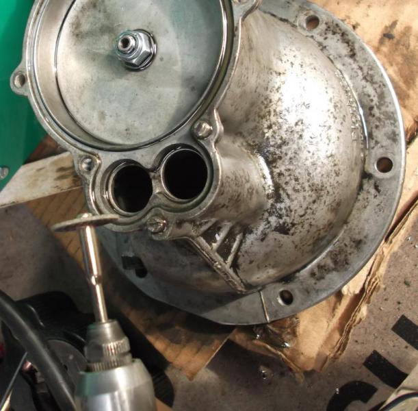 I found that that doesn't work – the metal is too soft. Method two => Getting angry – clamping on mole grips and trying to get the stub loose that way.  This doesn't work either – the metal is too soft. Method three => Drilling out a hole and using easy outs / screw extractors was next.  You need to drill a hole in the stub of the screw thread (see below for tips) and then tap a screw extractor into place whilst using either an adjustable spanner or a tap holder (shown in picture) to turn the screw so that it comes undone.  This method can work quite well but failed to do so in this situation because of the amount of corrosion in the threads. You must always be careful when using screw extractors because if you snap them off in the hole you make your life even more difficult because the metal of a screw extractor is normally much much harder than the metal of the screw stub. I decided not to have a snapped off screw extractor in my vacuum pump body. Method four => Drilling out the stub and repairing the thread if necessary. Before you start thinking about drilling out an old screw you need to be remind yourself that this is a destructive method. This process is a process of damaging something – you are breaking it to make it better. You need to break it in a beneficial way – otherwise you could be buying a replacement vacuum pump. First step is to flatten off the top of the screw stub sticking out of the vacuum pump body.  The best tool in the hands of a DIY mechanic for this job is a hand file. Power tools with cut off disks are a potential kiss of death especially if you use a too thick cut off disk and end up with a burr the size of Oregon on the end of the stub. You want to try and make the end of the stub as round as possible for the next step. Once you have a flat head on the end of the stub the plan then is to try and drill a pilot hole vertically through the centre of the screw stub. If you have a pillar drill this is the ideal bit of kit but don't forget to check that the working table is level.   I imagine most people on the forum don't have a decent pillar drill – the one in the picture above is crap; I bought it for another reason but that's a different story... If you are new to this I advise you to consider using one of these...  ...rather than grabbing your heavy cordless screw driver with the 18 volt super large NiCAD battery on the end of it. Try and find the lightest most controllable drill for this job. If your (cordless) drill has a tendency to be either off or giving you 10,000 rpm then that isn't the drill for you. Next step is to aim the end of the drill bit in the centre of the flattened head of the screw stub. Some people will say to use a centre punch for this – you can; but my experience with the inexperienced is that that can also be a bit of a steep learning curve. Pick out a small – say 1mm drill bit. Fit it in the chuck. Notice how fragile it is! Hold the drill as vertically as you can and drill until you think you have a little dent – a start – in the top of the stub. Stop and use your Mk1 eye ball to see if you got the centre or not. This is why you wanted a faithful round shape in the flat top of the stub. You want the centre.   If you didn't manage to get it first time – don't worry – with practice you can learn how to “drive” the bit about the top of the flattened stub surface. Tilt the drill at a slight angle and try to push the hole towards the position where you wanted to make the start in the first place. Don't push too hard you'll snap the bit. This is a skill that takes a bit of time to learn. Which ever drill you are using make sure that you use oil to help cut your way into the screw stub – this helps to prolong your drill bit's life. 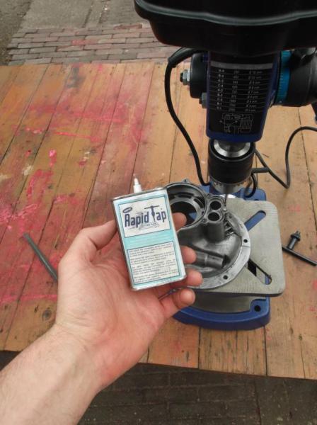 If you are drilling into a blind hole the idea is to try and drill down the centre of the stub with a pilot drill. You then gradually make the hole larger with the next size drill bit in your set until you reach the diameter of the screw stud just before the threads start. If you've been good you should probably be able to distort the remaining thin part of the threads with say a flat blade screwdriver and peel them away from the sides of the hole. With luck you can go deep enough so that you can run a tap down the hole to cut out the remaining parts of the screw thread. If you are drilling out a screw that is in a “through hole” you might be lucky enough to pull away the threads from a pilot drilled hole at the top and then with a drill, drill on through unsticking the stub. This is a little bit like the method of using left hand drill bits to back out the snapped stub – but because it is a through hole you can use a normal bit and keep on going.  It is always a good idea to clean out the threads after drilling with a tap.  If you have messed it up you need to drill a larger hole and fit a threaded insert – V-coil  This needs to be drilled vertically – you might want to go and find someone with a pillar drill for this – though it is often difficult to stop small diameter drill bits from bending to the wonky shape of a badly drilled hole. After you've finished drilling out screws don't forget to clean the whole pump body to make sure you don't leave any swarf behind.
__________________
1992 W201 190E 1.8 171,000 km - Daily driver 1981 W123 300D ~ 100,000 miles / 160,000 km - project car stripped to the bone 1965 Land Rover Series 2a Station Wagon CIS recovery therapy! 1961 Volvo PV544 Bare metal rat rod-ish thing I'm here to chat about cars and to help others - I'm not here "to always be right" like an internet warrior Don't leave that there - I'll take it to bits! Last edited by Stretch; 06-10-2013 at 09:52 AM. Reason: Added pictures
|
|
#8
06-09-2013, 07:02 AM
|
||||
|
||||
|
Rebuilding an OM61X piston vacuum pump reassembly
By now you should have a nice clean pump body and either a repaired cam follower arm with new bearings or a new replacement part. Make sure that the rest of the parts are clean and ready to go. The part number for the new seals set is 000 586 17 23. I'm trying to find a way of obtaining the copper impregnated PTFE piston seal here => Question about OM61X piston vacuum pump parts. If anyone can help with a solution I'll be interested to hear from you!
Reassembly is quite straight forward – it is the reverse process of taking it to bits. I'll attempt to shut up and just show the pictures...   Notice the different sized holes in the caps that go at each end of the springs... 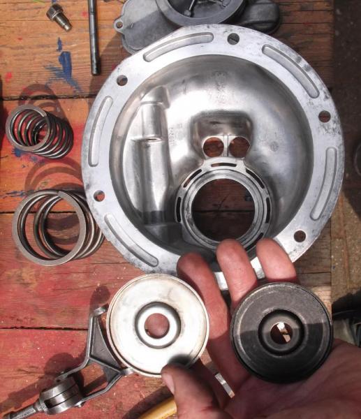 ...the one with the big hole goes closest to the piston.  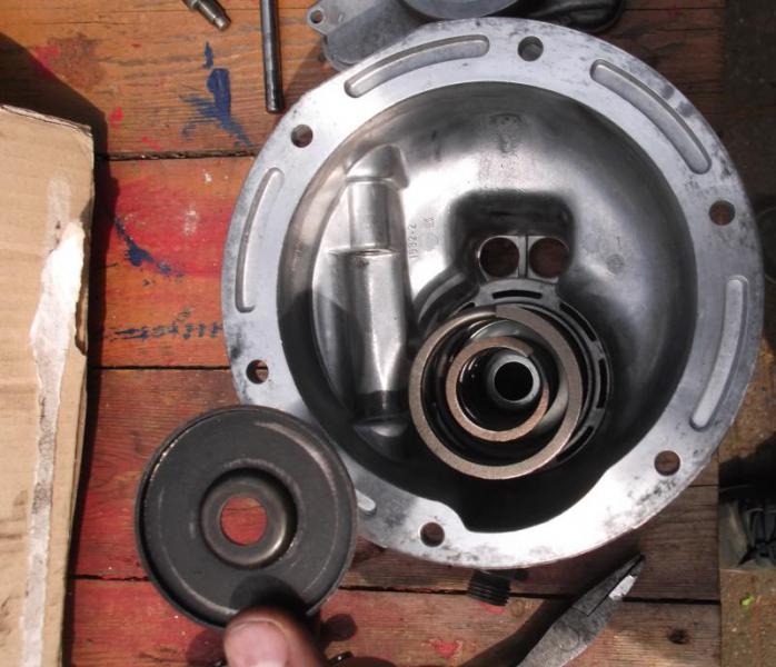  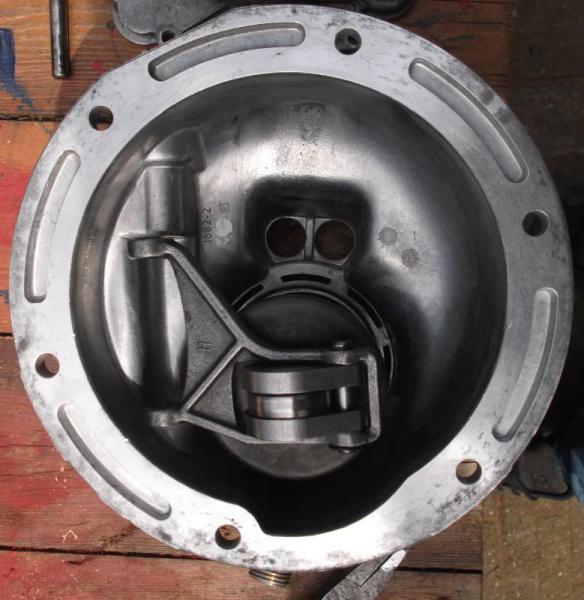 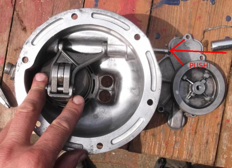 Tap pivot pin home with punch and light weight hammer   Apply a light coat of low melting point grease to pump body bore and the outer part of the PTFE piston seal. (I've put on too much for photographic enhancement!)     I could have used my trusty hydraulic press to compress the springs for the next bit but to show you all that a G-clamp and a bit of wood will do just as well here's the proof.   When the piston return springs are compressed and the piston starts to move up the bore you know that the piston is seated correctly. You can then do up the (new) stiff nut after fitting the washer of course.  Now you can fit the valves and the rest of the sealing gubbins...    ...and fit the cover.  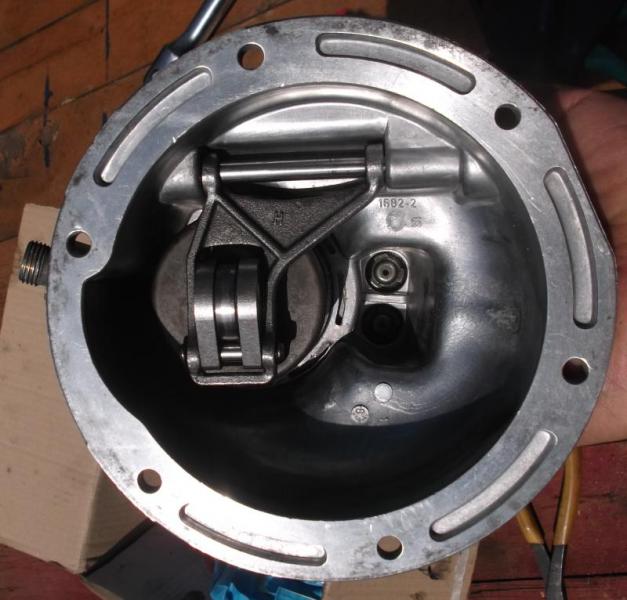 I've used M5 Allen headed screws with Gucci washers because Allen head screws are easier to drill out than slotted screws (as part of the pilot hole has been made for you). Smearing these cover screws with copper ease isn't a bad move considering how these buggers can corrode in place.
__________________
1992 W201 190E 1.8 171,000 km - Daily driver 1981 W123 300D ~ 100,000 miles / 160,000 km - project car stripped to the bone 1965 Land Rover Series 2a Station Wagon CIS recovery therapy! 1961 Volvo PV544 Bare metal rat rod-ish thing I'm here to chat about cars and to help others - I'm not here "to always be right" like an internet warrior Don't leave that there - I'll take it to bits! Last edited by Stretch; 06-09-2013 at 12:46 PM. Reason: Added pictures
|
|
#9
06-09-2013, 07:02 AM
|
||||
|
||||
|
Refitting your OM61X piston vacuum pump
To install your newly refurbished vacuum pump you are advised to turn the crank by hand so that when you offer the pump up to the engine the roller coaster cam surface on the timing device happens to be in a dip – ideally you want to align the wheel of the cam follower on the pump with this dip in the timing device roller coaster track.
The point of doing this is that you then don't need to apply more than 400N of force to compress the return springs in the vacuum pump. Make life easy for yourself and for the first two screws that hold the pump body to the block. Don't be tempted to turn the crank backwards - OM61X engines don't like their timing chains to be snagged. Don't be tempted to turn the engine at either the timing device or the camshaft. Ideally you should use the crank bolt. Connect the vacuum line to the input of the pump and away you go.
__________________
1992 W201 190E 1.8 171,000 km - Daily driver 1981 W123 300D ~ 100,000 miles / 160,000 km - project car stripped to the bone 1965 Land Rover Series 2a Station Wagon CIS recovery therapy! 1961 Volvo PV544 Bare metal rat rod-ish thing I'm here to chat about cars and to help others - I'm not here "to always be right" like an internet warrior Don't leave that there - I'll take it to bits! Last edited by Stretch; 06-10-2013 at 09:58 AM. Reason: Made a correction
|
|
#10
06-09-2013, 07:03 AM
|
||||
|
||||
|
Testing your OM61X piston vacuum pump
Once you've spent all that time re-building your pump you might want to test to see if it is working as designed. Alternatively you might want to test a vacuum pump before you decide to reseal it; you might want to do a before and after rebuild test. This procedure is given in chapter 43-660 in the FSM.
First thing to consider is the effect of absolute pressure. Where I live just a few metres above sea level the vacuum pump is able to “pull” or “suck” a greater pressure difference. With good seals a vacuum pump might be able to create a negative pressure close to 1 bar. At higher altitudes the vacuum pressure achieved on the gauge might not look so good. This doesn't necessary mean that your pump isn't working efficiently. (See LINK for more information) For this reason the FSM has specified that at an idle speed of 750 rpm the vacuum pump should achieve a 0.5 bar pressure (which I assume should be possible at most altitudes) within so many seconds when connected to the brake booster / and or the rest of the “comfort” vacuum system. To do this test you are meant to make up a little T section tube that you fit between the brake booster and the check valve. A link for making one of these bits for yourself is here LINK. Chapter 43-660 gives the piston vacuum pump connected to the brake booster 7 to 9 seconds at 750 rpm to reach 0.5 bar. The system is not meant to leak more than 0.2 bar in 30 seconds – it specifically says that a leak of 0.2 bar in 30 seconds is permitted; so there's a subtle difference that probably is a bit misconstrued in the translation from the German version (sorry I can't be bothered to check – I'd have to start Windows to see my German copy of the FSM...) The reason why Mercedes decided to provide test specifications for the vacuum pump when it is fitted to the brake booster and not just when there's a gauge fitted to the end of the pump is probably because the pump would evacuate the connection so quickly it would be difficult to measure. At 750 rpm you've got 12.5 cycles (or strokes of the piston) per second. As the pump should evacuate the volume of the brake booster and the line to the pump to 0.5 bar within 7 to 9 seconds that's 87.5 strokes for that volume if 7 seconds is achieved. The displacement volume of the OM61X piston vacuum pump is 7.85 cm3 (see below). Piston pumps are generally expected to have an efficiency of 85% to 90% so the pump should be able to shift about 6.67 cm3 per stroke or 83.4 cm3 per second at 750 rpm (taken with 85% efficiency). If anyone has a flow meter and wants to check that for me I'd be happy to hear from you! Another reason for adding this information is that people sometimes ask whether they can replace the mechanical pumps with electric ones – this estimated flow rate should give people a ball park idea of what is expected from the vacuum system on a W123 / W126 / W115 / W116 (although the W115 and W116 probably don't have the piston vacuum pumps fitted – only the diaphragm ones).
__________________
1992 W201 190E 1.8 171,000 km - Daily driver 1981 W123 300D ~ 100,000 miles / 160,000 km - project car stripped to the bone 1965 Land Rover Series 2a Station Wagon CIS recovery therapy! 1961 Volvo PV544 Bare metal rat rod-ish thing I'm here to chat about cars and to help others - I'm not here "to always be right" like an internet warrior Don't leave that there - I'll take it to bits! Last edited by Stretch; 06-09-2013 at 09:36 AM. Reason: Made a correction
|
|
#11
06-09-2013, 07:04 AM
|
||||
|
||||
|
OM61X piston vacuum pump science project (introduction)
Right folks that's the boring stuff over and done with! This is the real reason why I wanted to do this thread =>
Does the piston park? Yes or no? The debate raged on – well it didn't really – everyone was well behaved => VACUUM PUMP FAILURE! Are you neglecting yours??. The theory is that the suck from the vacuum is strong enough to hold the piston and the cam follower away from the roller coaster cam on the timing device. The force produced by a vacuum on one side of the piston is proportional to the area of the piston and the vacuum pressure. The piston diameter is 6.9 cm and so the area is 37.4 cm2. At a negative pressure of 1 bar the force (of the suck) is 373 Newtons (N) {Force = pressure X area}. This force is working against the force of the return springs. Please note a true vacuum of 1 bar gauge pressure is like the holy grail of vacuum pump capabilities – on this planet it can't suck any more than this! In the thread linked above the maximum negative pressure is quoted to be more likely 25” hg which is 0.847 bar which then provides a force of 317 Newtons. To calculate the force of the return springs I thought it was an ideal opportunity to demonstrate how you can calculate the force – or more importantly the linear stiffness – of a coil spring; and how to verify this calculation with a measurement. This is fun high school project stuff for geeks. It is also useful for other purposes such as uprating valve springs (I'll show how to estimate valve bounce in a bit) or customising new throttle linkages in modified vehicles etc.
__________________
1992 W201 190E 1.8 171,000 km - Daily driver 1981 W123 300D ~ 100,000 miles / 160,000 km - project car stripped to the bone 1965 Land Rover Series 2a Station Wagon CIS recovery therapy! 1961 Volvo PV544 Bare metal rat rod-ish thing I'm here to chat about cars and to help others - I'm not here "to always be right" like an internet warrior Don't leave that there - I'll take it to bits! Last edited by Stretch; 06-09-2013 at 12:34 PM.
|
|
#12
06-09-2013, 07:04 AM
|
||||
|
||||
|
How to calculate and measure coil spring linear stiffness
Most of the information presented in this section comes from a great book - “Spring design and manufacture” by Tubal Cain ISBN 978-085242-925-9. This Tubal Cain is an English chap who has written loads of good technical books not the other good (American?) Tubal Cain who has lots of interesting machining videos on youtube. It seems to me that anyone who is called Tubal Cain is a good bloke!
So far I've only found these equations mentioned on this internet site => Springs. But I'll put them here as well for the sake of keeping the flow going.   I've presented the equations in a slightly different format from the site linked above – they are more in keeping with the book I referenced above. Below you can see a list of properties for the two springs in the OM61X piston vacuum pump.  Stiffness is defined as the force required to compress or extend the spring by a unit amount. I'm using the metric system and because the springs are small the values are coming out as Newtons per millimetre (N/mm). This means that to compress the large spring by 1mm you need to apply a force of 13.48 N. Plotting applied load (or force) against the deflection of the spring you end up with a straight line relationship. This straight line relationship is often referred to as a linear relationship. If the graph was a curve it would be non-linear. The spring will “go non-linear” when it reaches the extremes of its travel; in compression the number of independent coils (n) reduces as the coils begin to touch; in tension the effective diameter of the coil spring (D) reduces or necks. To check the calculation given above I devised a pretty gash way of measuring the force and deflection of each spring. In an ideal world I'd use a decent way of measuring spring deflection with say a depth gauge or a LVDT but the equipment I've got wouldn't allow it. In an ideal world I'd have used a calibrated force gauge to measure the force – something like that is beyond my play budget at the moment. All I had was an old fashioned set of bathroom scales. There is no way that these measurements that I have made are reliable in any commercial sense (let alone to a decent research standard) but they do show the general method that can be applied and copied. The measurements I made, however, do provide a good indication of what is likely and because I'm comparing these measurements with an established theory they show that they are kind of believable! The measurements are only presented as an indication of what's likely to be going on. They are made to a unique guy in a shed standard that isn't recognised by ISO. Feel free to take these results with a pinch of salt or not... To make the measurements I used my hydraulic press to compress the spring. If I had been able to connect a low pressure hydraulic gauge I could have worked out the applied force at the end of the piston but I went for a quicker option – using the bathroom scales! Old fashioned scales are not known for being particularly accurate but I checked them with some known weights and they were coming up with consistent repeatable values. (Please note digital bathroom scales are of no use for this method as they tend to reset themselves at low values) This was a quick and dirty solution that didn't involve too much messing about.  If I could have got my depth gauge to fit then I would have used that to measure the deflection but again no such luck. Quick and dirty solution number two was to mark the deflection on a back of an envelope.  This method doesn't seem very accurate – I know – but take a look at the results. I made three sets of measurements compressing each of the springs in my piston vacuum pump. These results are presented as force (kg X 9.81 m/s2) versus deflection.   Stiffness is the slope of these lines so you can see I measured a stiffness of about 11.2 N/mm for the big spring (compare with calculation of 13.48 N/mm) and I measured about 10.2 N/mm for the small spring (compare with calculation of 12.24 N/mm). Not bad eh? Especially when you consider this has been achieved with a bit of paper a ruler and a some dodgy bathroom scales. I was planning to build my own spring force / deflection measuring rig as commercially these are seriously expensive – I'm not so sure I'll bother now... Next thing I wanted to check was how the two springs behaved together one inside the other just as they are fitted in the vacuum pump. Theoretically the stiffness should be added together because they are in parallel. This is like saying that they are in operation side by side rather than in series which would be one spring on top of the other. Making a measurement as before came up with these force verses deflection lines.  As you can see the measured stiffness (22.1 N/mm) is about the same as the combined calculated value (13.48 + 12.24 = 25.72 N/mm) and the combined two independently measured values (11.2 + 10.2 = 21.4 N/mm). Again not too bad. It is all believable. This has all been very clever (I can hear some of you saying) but what's the point? Well with all of this data I can work out how much the force the return spring is pushing the cam follower onto the roller coaster cam on the timing device. I could of course have just measured the deflection of the cam follower being pushed into an assembled vacuum pump – but where's the educational fun in that? To be honest I did that anyway – so here's the result – but don't forget I also had to check the validity of using those dodgy bathroom scales...    From the graph above you can see that the return springs apply more force to the cam follower than the opposing force provided by the vacuum “suck” (this has been calculated above to be about 317N in the most likely situation to 373N in the most perfect case possible on planet earth where an OM61X is likely to be operating). When fully released the minimum force needed to move the piston is about 400N; and when pushed to the end of the stroke you need about 620N. But this is just the static case – what happens when the engine is running?
__________________
1992 W201 190E 1.8 171,000 km - Daily driver 1981 W123 300D ~ 100,000 miles / 160,000 km - project car stripped to the bone 1965 Land Rover Series 2a Station Wagon CIS recovery therapy! 1961 Volvo PV544 Bare metal rat rod-ish thing I'm here to chat about cars and to help others - I'm not here "to always be right" like an internet warrior Don't leave that there - I'll take it to bits! Last edited by Stretch; 06-09-2013 at 12:37 PM. Reason: Added pictures
|
|
#13
06-09-2013, 07:05 AM
|
||||
|
||||
|
Estimating valve bounce
As some of you might be able to detect, I've been looking for an excuse to present this method for a long time. I was planning to include it in this thread (OM617 (non turbo) cam profile specs, piston height specs etc) but this one will do just as well as I still haven't managed to finish off the measurements I want to make in that thread.
Valve bounce occurs (in engines) where the valve spring isn't strong enough to hold the valve in the desired position – the valve opens at the wrong moment. This is a little bit like “getting some air” when you drive over a humped back bridge too quickly – here the weight of the car and the effect of gravity isn't enough to keep the wheels on the ground. The same thing can happen to a valve moving in an engine and the same thing could happen to the piston in the vacuum pump. Generally speaking valve bounce is considered to be a bad thing! Did Mercedes design the piston to “park” at high engine speeds? When I first took off my vacuum pump and I saw the roller coaster track on the timing device I thought – sine wave! This is an unusual shape to make a cam; and generally speaking designers try to avoid sinusoidal excitation. For this reason I thought it might be “close to sinusoidal” rather than actually being sinusoidal, so I thought I'd better go off and make a quick measurement just to make sure. I whacked a DTI on a magnetic base and measured the clear silver wear line on the surface of the roller coaster track on the timing device. The position of each height measurement was ascertained by noting the position of the cam shaft timing wheel (as I have done previously in the measurements of OM617 cam surfaces in the thread linked above).  I also measured the piston deflection of the pump when fitted to the engine (without springs) just in case anyone was interested in the effect of the cantilever arm and the cam follower – there isn't one.   As far as I'm concerned that's sinusoidal – even though the measurements were made in a bit of a rush. It can be assumed that as the motion of the piston follows that of the roller coaster track on the timing device the following calculations are applicable. This is the case so long as there is no loss of contact between cam follower and cam (roller coaster track). Spread sheet calculations of the dynamic motion of the piston in the vacuum pump are simple when you accept that the track is sinusoidal. In the situation where a cam surface isn't easy to define with a mathematical relationship you can use a measurement of the surface (perhaps using the method shown in the thread I'd just provided a link for) for the method shown below. In this case – for the cam surface on the timing device – the first step is to plot a sinusoid as a function of distance. This distance was measured directly from the wear marks on the surface on the timing device.  For a specific rotational speed you can calculate the time it takes for the cam follower to follow the surface of the cam. The average velocity can be calculated for each step change in time and then the acceleration can be calculated from the velocity. You can put all of this in a spread sheet.  You get the following results of displacement and acceleration for the vacuum piston pump at an engine speed of 800 rpm.  From this graph you can see that the maximum acceleration occurs at a specific time which relates to a specific cam position. In my spread sheet this comes out at about 270 degrees. This is a bit of an approximation as it depends on the spacing I have chosen for distance across the surface of the cam – I am using discrete data points; something could be happening in between! But as far as I'm concerned this result is good enough for demonstration purposes on this forum (I'm not writing research papers any more). A smart Alec should be able to calculate an analytical result for this sinusoidal case if they want – but really I've wasted enough of my time on this already (please note on a more complex cam profile it is probably easier to stick with this numerical method). As I now know (more or less) when the maximum acceleration occurs I can plot this out for all expected engine speeds.  As the force produced due to the piston and cam follower rolling over the cam surface is proportional to the mass of the moving parts and the acceleration calculated above the estimated force can be plotted as shown here. (Force = mass X acceleration)  We can now compare this force directly with the measured forces or calculated forces of the vacuum pump springs with or without the effect of vacuum “suck” and reach the conclusion that Mercedes probably didn't design the piston to park. I'm not sure they designed it all that well though! At low engine speeds the combined force due to acceleration and the maximum likely vacuum pressure is unlikely to over come the minimum reaction force of the two return springs in the vacuum pump. For example at 800 rpm the force due to acceleration is 20 N. Combine this force with a sucking pressure of 317N we're lower than the lowest measured reaction force of 400N. At higher engine speeds, however, say 3000 rpm the estimated force due to acceleration is about 100N. Combine this with a sucking force of 317N and we've potentially got trouble at the bottom of the roller coaster track as this force is greater than the reaction force of 400N. The spring reaction force quickly corrects this though as it can apply up to 620N in reaction force as the reaction springs get compressed. At 5000 rpm we have the biggest likelihood that the cam follower rattles on the surface of the timing device cam. The force due to acceleration is about 275N and with a realistic perfect vacuum system we've got a combined 592N versus 400N when the piston is closest to the timing device. For the majority of the piston pump's stroke the return springs' reaction force is inferior to the combined force of suck and acceleration due to motion over the cam surface. If I've got my numbers right – and that could be a problem with me! - and you're in the habit of driving long distances with your OM61X revving at about 4000 rpm or more it seems as though you're better off doing that with a leaky vacuum system! In reality, however, the effectiveness of the piston vacuum pump might be limited at these high speed cycles per second (5000 rpm = 83.3 cycles per second = 83.3 Hz). I don't know for sure so I've got a little bit of bed time reading to do. Please note (1) the numerical method shown above is prone to rounding errors and accumulative errors. Also it is a linear method that indicates when valve bounce may happen. It is not able to calculate what will happen if loss of contact between the cam and the cam follower actually occurs. This method is also presented in the Tubal Cain book I mentioned previously. Don't forget with knowledge comes great power – and sometimes with great mistakes too! Please note (2) this is not the end of the story! (Just when you thought it was safe...) I haven't considered the following:-
__________________
1992 W201 190E 1.8 171,000 km - Daily driver 1981 W123 300D ~ 100,000 miles / 160,000 km - project car stripped to the bone 1965 Land Rover Series 2a Station Wagon CIS recovery therapy! 1961 Volvo PV544 Bare metal rat rod-ish thing I'm here to chat about cars and to help others - I'm not here "to always be right" like an internet warrior Don't leave that there - I'll take it to bits! Last edited by Stretch; 06-09-2013 at 12:44 PM. Reason: Added pictures
|
|
#14
06-09-2013, 05:09 PM
|
||||
|
||||
|
Epic! Thanks.
My only question would be that I thought that the bearings were supposed to be "open" i.e. without dust covers. You appear to be using "sealed" bearings.  Will these get enough lubrication over time? Am I missing something? On the topic of the vacuum pump "parking", thanks for the mathematical proof of the reality that they do not park. Actually, if you think about it, if the vacuum that the piston produced were enough to pull the piston into a "park" position by applying the vacuum to the other side of the piston, it would be producing more vacuum than it could produce - the excess vacuum being used to pull it into a "park" position. If this were true, we could probably adopt that principle into a perpetual motion machine by using the excess vacuum to do other work  . .I've got a vacuum pump I want to rebuild, just trying to figure out the optimum bearing replacement. Again, thanks!
__________________
Current Stable
|
|
#15
06-09-2013, 10:50 PM
|
||||
|
||||
|
You know, I just never get sick of your write ups! Excellent, well done!
__________________
1980 300TD, SOLD 1984 300TD, 275K  1999 C230 K Black & Tan 2013 C250 Black 1974 CJ5 Red You might faint from the fight, but you're gonna find it. Every challenge could have paradise behind it. -John Popper-
|
|
| Bookmarks |
|
|


 Linear Mode


