 |
 |
 |
 |

|


|
|
|
|
|
|
#1
|
||||
|
||||
|
Mechanical to Electronic Speedometer Conversion
I'd like to use this thread to tee up a discussion on the overall topic of electronic speedometer options for our vehicles.
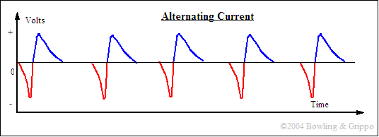
I've run into the problem with my diesel conversion (617 into a 380SL) and ROLLGUY is having a similar problem on his transmission swap of a 722.4 into a 300SD that originally came with an electronic speedo 722.3. In both cases we thought that a tailcone swap would work but it is now painfully obvious that the two 722 transmissions (.3 vs .4) have different tailcones. It is still possible that a tailcone from a C220 or a C280 will get the job done, but additional research points to that being a somewhat dubious proposition. I'll explore some of the more exotic solutions in supplemental posts, but I'd like to set the stage for a discussion and additional options. First, everything I can find points to the notion that the electronic speedometer pickup on the 722.3 and likely the 722.4 as well is a variable reluctance system consisting of a trigger wheel and a sensor. Here is a picture of the internals of a 722.3 tailcone (from the 380SL) where the 4 "spoke" trigger wheel is clearly seen mounted to the parking pawl. The sensor reads each revolution through a voltage change from negative to positive.  The wave form looks something like this  An in depth discussion of VR devices for triggering spark in Megasquirt using an EDIS device is here- Distributor Pickups Trigger wheels take many forms and the following image shows some of the kinds that have been used in ignition applications generally as part of a fuel injection system.  The first solution I'd like to toss out for discussion and critique is to create a "virtual trigger wheel" using the drive shaft as a base. Here's a graphic of what I have in mind. The green are the "teeth" of the virtual trigger wheel, the purple is the stock MB sensor and the red is a custom bracket with appropriate adjustments for setting the clearance.  This proposed solution would use 4 carefully sized, fabricated and balanced steel "teeth" that would be epoxied to the drive shaft at exactly 90 degree intervals, as close to the front end as feasible. Taken in cross section we would have the equivalent of a 4 tooth trigger wheel, something like this.  It would not be prudent to rely on simple epoxy as a bonding agent, so I would use fiberglass, kevlar or carbon fiber cloth ribbon and epoxy to create a composite "band" around the driveshaft. Since these materials are quite light and would be evenly distributed, adverse balance effects should not be introduced. Rather than mount the sensor to the tunnel I would mount it to the rear transmission mount bracket to eliminate all but the tiniest and insignificant relative motion of the transmission and the driveshaft. It seems as though this strategy would replicate the internal operation of the Mercedes system with an external "universal" alternative using the stock sensor, wiring and electronics which could be fabricated with relatively simple tools and materials. Here's an article with a lot of great information on the subject of VSS (Vehicle Speed Sensors) - VSS Where am I wrong and what have I missed?
__________________
Current Stable
Last edited by mach4; 02-13-2012 at 01:37 AM. Reason: more info |
|
#2
|
||||
|
||||
|
In the previous post I discussed the idea of creating a virtual trigger wheel and using the stock MB speedometer sensor. In this post I want to take a look at another potential alternative.
This idea comes courtesy of Patrick Schalles in an article titled How To: Installing a Universal Magnetic Pickup Speedometer Instead of using a MB speedometer he is using a universal speedo e.g. the AutoMeter one. Instead of using a variable reluctance system he is using a Hall-effect system using magnets instead of "teeth" on the driveshaft. This sensor kit is about $25 from Rostra Precision Controls.  This system uses a different signal but from his article it appears that we might be able to use this signal by putting it through a GM VSS Buffer to convert the AC signal to a square wave signal. I'm not an electrical engineer but it seems plausible that the signal from the VSS Buffer might be able to be fed into the wiring of the MB sensor and get a signal that way. If this is possible, it means that instead of relatively close sensor-to-trigger-wheel gaps we could theoretically go with the easier and more forgiving tunnel mounting and 1/2" recommended gap.  I actually spent about an hour looking for one of these devices at the JY this weekend to no avail. A follow on solution using this strategy might be to somehow insert the internals of an AutoMeter speedometer into the MB cluster. Probably not something I'd try, but maybe a path for someone to pinneer. Anyone have any opinions about whether this kind of a signal might be suitable for a direct feed into the MB system?
__________________
Current Stable
Last edited by mach4; 02-18-2012 at 11:55 PM. |
|
#3
|
||||
|
||||
|
So right in the middle of my research and thinking about a conversion from mechanical to electronic speedometer in my diesel conversion of a 380SL comes this tidbit in a Question Posed on FixYa. The Question is
Quote:
Quote:
If the speedo uses the ABS sensor, what is the purpose of the transmission speed sensor? Bogus? If on the other hand this is the source of the speedo signal, problem solved. 
__________________
Current Stable
|
|
#4
|
||||
|
||||
|
I call BS. What is the purpose of the cable from the tranny to the speedo if the ABS wheels sensors drive the speedo? Conversely, how is the ABS controller connected to the speedo?
Your initial proposal is the most elegant. Sixto 87 300D |
|
#5
|
||||
|
||||
|
I thought of a more evasive solution, but I probably will not do it because of the risk involved (ruining the parts I have). I will try to describe it, as I have no way of illustrating it otherwise. I thought of making a fixture that would index the center of the tail cone shaft in relation to the mounting surface. I would then have my machinist friend fly cut the nose (the area of the speedometer sensor) of both tail cones so that the electric portion (nose) can be welded on to the housing portion of the cable tail cone. I would then end up with a tail cone that fits the 722.4 trans, but has the fitting for the electric pickup. The one problem I see is that I would need to remove the plastic piece that is inserted in the aluminum casting that the sensor fits into that keeps fluid from pouring out when the sensor is removed. I have a feeling that it is not removable without breaking it. My machinist has the capability to do the cutting and welding, but the whole job may cost more than it is worth. The other problem, is that I am quite sure that the gears in the cluster are bad as well (common with the 126). It has bee suggested that I just find a way to put a 123 (cable operated) speedo in the 126 instrument panel. I am not sure if this is possible, but I might try it BEFORE cutting and welding of the tail cones. I have some 123 speedo's and cables in stock, so if I ruin one it is no big deal. The car is just a beater car anyway, but my friend needs the odometer to work in order to insure it. If the instrument panel looks weird, it is no big deal to him as long as the odo works.
Another thought I had was concerning the 4 spoke trigger wheel. Could it be mounted externally (on the driveshaft maybe)? I thought that maybe it could welded on the nose just behind the flex disc, but there might not be enough space there. Another option would be near the center support where the shaft is thinner. The problem here would be trying to keep the proper distance between the sensor and the trigger (rubber mounted bearing movement). I am just throwing ideas out here, so anyone feel free to post your opinions/suggestions. Thanks, Rich
__________________
All Diesel Fleet 1985 R107 300SLD TURBODIESEL 2005 E320 CDI (daily) LOTS of parts for sale! EGR block kit http://www.peachparts.com/shopforum/diesel-discussion/355250-sale-egr-delete-block-off-plate-kit.html 1985 CA emissions 617 owners- You Need This! Sanden style A/C Compressor Mounting Kit for your 616/ 617 For Sale + Install Inst. Sanden Instalation Guide (post 11): http://www.peachparts.com/shopforum/diesel-discussion/367883-sanden-retrofit-installation-guide.html |
|
#6
|
||||
|
||||
|
That's exactly what I thought - but it definitely had me thinking for a bit.
__________________
Current Stable
|
|
#7
|
||||
|
||||
|
Quote:
 And the article I linked to had this image of a trigger wheel attached to the driveshaft at the differential.  That appears to be a 40 tooth wheel, but it would work just as well with a 4 tooth wheel. I thought it was very elegant the way it piece was designed - no welding and no cutting. 
__________________
Current Stable
|
|
#8
|
||||
|
||||
|
Quote:
Although we haven't heard from him in a while, evidently this has worked out well. .
__________________
1983 123.133 California - GreaseCar Veg System |
|
#9
|
||||
|
||||
|
Well I can now state without doubt that the initial solution to turn the driveshaft into a trigger wheel by gluing "teeth" to it and using the stock sensor with a custom bracket does work.
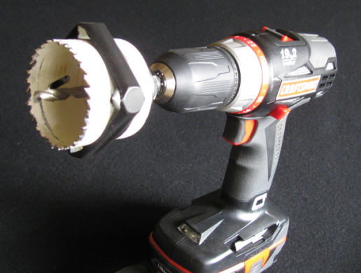
Here's my "driveshaft-with-trigger-teeth" test setup.  I crawled under the car and held my "driveshaft" in close proximity to the sensor and indeed got a speed reading. (Sorry for the poor picture - it's a frame grab from a video as I couldn't be under the car and in the cockpit at the same time to take a picture) This is probably a worst case scenario as my "teeth" in this test were nuts and I'm sure the hole in the middle made the signal appear to be weird to the system, so well proportioned teeth will definitely provide a cleaner signal. And trying to hold a drill and a sensor steady under the car is not a great way to maintain any kind of consistent sensor-tooth gap.  As far as I'm concerned, I'll consider this problem solved and move ahead with fabricating a bracket and cutting and mounting my "teeth".
__________________
Current Stable
|
|
#10
|
||||
|
||||
|
I thought you said something about gluing metal on the driveshaft, and that is why I asked about attaching the stock trigger wheel to the driveshaft somehow. I just got out from under the car putting the driveshaft back on, knowing that I won't need to get back into the rear of the trans to make an electric pickup work. I measured the trigger wheel that I pulled off of the park pawl gear, and it is about 35mm inside diam. The smallest part of the shaft near the flex disc is about 47mm. I am glad you tested your theory out. Could something be welded (instead of glued) on the driveshaft resembling the trigger wheel? That sounds like the direction you are headed, but I will wait and see what you come up with.
__________________
All Diesel Fleet 1985 R107 300SLD TURBODIESEL 2005 E320 CDI (daily) LOTS of parts for sale! EGR block kit http://www.peachparts.com/shopforum/diesel-discussion/355250-sale-egr-delete-block-off-plate-kit.html 1985 CA emissions 617 owners- You Need This! Sanden style A/C Compressor Mounting Kit for your 616/ 617 For Sale + Install Inst. Sanden Instalation Guide (post 11): http://www.peachparts.com/shopforum/diesel-discussion/367883-sanden-retrofit-installation-guide.html |
|
#11
|
|||
|
|||
|
A VR sensor interface is set up for a certain waveform amplitude range and to the resistance of the sensor itself. Try to use the original sensor and try to use the same air gap. That way you don't introduce variables that could cause problems that are murder to diagnose.
I like the idea of the tabs on the driveshaft. Very simple. |
|
#12
|
||||
|
||||
|
Quote:
A good epoxy is likely enough, but I wouldn't trust that. My insurance solution is to get some fiberglass, kevlar or carbon fiber tape and using epoxy, layup a ribbon around the driveshaft. They make aircraft wing spars out of carbon fiber so I know it would be more than strong enough. The other reason for going that route is for weight. If your "teeth" are the same weight and the epoxy and cloth is evenly distributed around the driveshaft, any weight discrepancy is likely too small to measure. If you've never laid up fiberglass (or carbon) here's a little video that will give you a pretty good idea about the process. Hand laid fiberglass body tube - YouTube For our purposes the analogy is that the cardboard tube is the driveshaft and instead of laying up a 3-4 ft segment for a rocket fuselage, we're laying up a 3-4 inch segment with 4 steel teeth in the middle of the segment. Fiberglass is very much able to go around 3 dimensional curves so it will not be a problem. I'd probably be happy with 3 layers, 4 at the most for fiberglass and 1-2 layers for carbon fiber (just cut the top layer cleanly at the starting point of the first layer to maintain balance) If you wanted to be really trick, you could create some fillets around your teeth using a microballoon-epoxy paste to eliminate the bubbles that will be present between the driveshaft and the fiberglass where the teeth are. In the image below, the purple is the cloth and the green is the microballon fillet. You will also probably want to grind a little concave surface into your teeth to get a good bonding surface.  Also note how trigger wheel teeth are generally wider at the base than at the top. This gives a cleaner signal.  You could use AeroMarine 300/11 Epoxy ( AeroMarine Products- Epoxy Adhesives) or for the finest materials you could use aircraft grade fiberglass tape and epoxy resin from Aircraft Spruce. (Composites from Aircraft Spruce )
__________________
Current Stable
|
|
#13
|
||||
|
||||
|
Do you think you need all that? I'll bet the double sided adhesive they use for wheel weights will last the remaining life of the car.
Sixto 87 300D |
|
#14
|
||||
|
||||
|
Quote:
But if one did come loose it could cause some damage as well as throw the driveshaft significantly out of balance. Whereas laying up a composite retaining ring would guarantee long-term integrity.
__________________
Current Stable
|
|
#15
|
||||
|
||||
|
A wheel weight would be installed on the inside of a wheel (centrifugal force is against the inside of the rim), whereas the centrifugal force on the driveshaft will want to throw off the tabs or whatever was glued on. I think I could make some pieces of steel that would mimic the tabs on the trigger wheel, and weld them on. I doubt the balance would be affected enough to cause a problem. If I did it correctly, the circumference of the finished tabs would be the same as the stock trigger wheel. The speedometer would not know the difference.
__________________
All Diesel Fleet 1985 R107 300SLD TURBODIESEL 2005 E320 CDI (daily) LOTS of parts for sale! EGR block kit http://www.peachparts.com/shopforum/diesel-discussion/355250-sale-egr-delete-block-off-plate-kit.html 1985 CA emissions 617 owners- You Need This! Sanden style A/C Compressor Mounting Kit for your 616/ 617 For Sale + Install Inst. Sanden Instalation Guide (post 11): http://www.peachparts.com/shopforum/diesel-discussion/367883-sanden-retrofit-installation-guide.html |
 |
| Bookmarks |
|
|