 |
 |
 |
 |

|


|
|
|
|
|
|
#166
|
||||
|
||||
|
I've been trying to figure out how best to document the maze of vacuum lines in preparation for moving from one vehicle to the other.
What I'm playing with is using little paint dots of different colors to signify where the lines go. Each device has a different color and each line has a different number of dots.  Anyone else discover a good and hopefully mostly-permanent labeling system that doesn't use tape flags?
__________________
Current Stable
|
|
#167
|
||||
|
||||
|
Sounds good. As usual your fabrication is a work of art!

__________________
[SIGPIC] Diesel loving autocrossing grandpa Architect. 08 Dodge 3/4 ton with Cummins & six speed; I have had about 35 benzes. I have a 39 Studebaker Coupe Express pickup in which I have had installed a 617 turbo and a five speed manual.  [SIGPIC] [SIGPIC]..I also have a 427 Cobra replica with an aluminum chassis. |
|
#168
|
||||
|
||||
|
Quote:
Should look like this, but with the electronic pickup instead of the mechanical gears. 
__________________
Current Stable
|
|
#169
|
||||
|
||||
|
In continuing my research on the vacuum system I've got two questions I haven't been able to find an answer to.
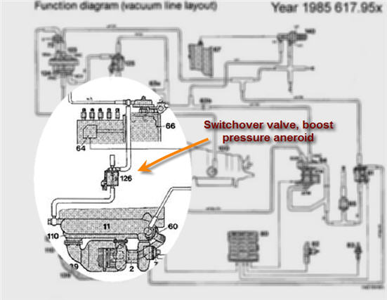
[1] Switchover valve, boost pressure aneroid - As shown below in a detail of the functional diagram of the vacuum line layout, this valve has a vacuum input from the intake manifold and an output to the ALDA. But it also has an electrical connection as shown in the second image, that disappear into a large wiring harness bundle. This electrical connection is not shown in the diagram (it doesn't connect to the #80 EGR Controller for example) Where does this electrical connection go and what does it hook up to?   [2] Switchover valve, vacuum transducer - this device takes an input from a coolant temp switch. Again, I can't seem to find an electrical diagram of this system, but I would kind of assume that since it is a two wire connection and #20 is a switch grounded to the block, I could take any switched hot to one lead and to the switch for the other and get the proper operation. Does this make sense?  Thanks
__________________
Current Stable
|
|
#170
|
||||
|
||||
|
1) The switchover valve interrupts the pressure signal to the ALDA. There isn't any vacuum to speak of in an engine without an airflow throttle. There are two wires to the switchover valve - constant +12V when the engine is running, and ground from the overboost switch on the intake manifold.
2) Yes. Sixto 87 300D |
|
#171
|
||||
|
||||
|
Quote:

__________________
Current Stable
|
|
#172
|
||||
|
||||
|
Quote:
__________________
John HAUL AWAY, OR CRUSHED CARS!!! HELP ME keep the cars out of the crusher! A/C Thread "as I ride with my a/c on... I have fond memories of sweaty oily saturdays and spewing R12 into the air. THANKS for all you do! My drivers: 1987 190D 2.5Turbo 1987 560SL convertible 1987 190D 2.5-5SPEED!!!  1987 300TD 2005 Dodge Sprinter 2500 158"WB 1994GMC 2500 6.5Turbo truck... I had to put the ladder somewhere! |
|
#173
|
||||
|
||||
|
Quote:
 That large silver box on the left is the prominently labeled KE-Jetronic ECU for the 380SL and assuming I can pull that out with no ill effects, the EGR Control unit will drop right in. And if I'm really lucky, I can find the pinouts on the Jetronic and be able to use the power source downstream of the 380SLs OVP (over-voltage protection relay) and not have to wire in the one from the 300D.  For those that come along behind researching or executing a similar project, you might find my colorized vacuum cheat sheet handy for figuring out what's going on. (Full size image attached) 
__________________
Current Stable
|
|
#174
|
||||
|
||||
|
Pulled the huge connector cable to the Jetronic ECU expecting to see a jillion wires, and was surprised to see only 9 are actually used. I found an electrical diagram of the system (shown below) and verified that there are indeed only 9 connections.
Pin 2,4 - Oxygen sensor (Lambda input) Pin 5 - Ground (throttle switch grounds on WOT) Pin 6 - Idle Input to idle speed control Pin 7 - Fixed Ratio Input to idle speed control Pin 16 - Frequency Valve (trims fuel) Pin 18 - Ground Pin 8 - Power (from OVP) The fuel injection is actually an almost entirely mechanical system with Lambda control added for stoichometric operation at cruise.  To hook up the EGR Controller, I should have only 9 wires to bring through from the engine compartment and I can snag conditioned power and ground right out of the Jetronic harness. A lot better than what I was expecting! Vacuum and engine electrical are starting to make sense.
__________________
Current Stable
|
|
#175
|
||||
|
||||
|
Doesn't KE-Jet have a cold start valve and/or injector and a coolant temperature sensor? Is the idle circuit completely mechanical?
Sixto 87 300D |
|
#176
|
||||
|
||||
|
Quote:
It connects to stuff like the idle speed adjuster solenoid, lambda control module (Jetronic), rpm signal, coolant temperature, etc. I'm guessing I can eliminate that whole module as well; doesn't look like anything that would be useful... but more research is needed to know for sure.
__________________
Current Stable
|
|
#177
|
||||
|
||||
|
Having some trouble identifying the switches/sensors on the OM617.952.
So here's what I've got. #1 On the top of the head - [Edit: Almost entirely positive that this is the] temperature switch that is associated with the Vacuum Transducer Switchover Valve (#20) #2 In the thermostat housing - It is a VDO device, obviously a switch since it carries markings - 100C/95C, 6-24v 100W, 120C MAX, 4.75 (had a spare from a JY thermostat housing I took the info off of) [Edit: This then should be the switch to turn on the fans when the temp hits 95-100C] #3 Side of head - Might be the coolant sensor for the EGR or the sensor for the dash [Edit: Confirmed - this is the EGR Temperature Sensor] #4 Side of head - Might be the coolant sensor for the EGR or the sensor for the dash [Edit: Confirmed - this is the sender for the gauge] The ohm readings are at ambient (60F today). (And if #2 is a switch why is it showing 2 ohms? Defective??)  Side view of 3 and 4.  Any insight into whats what? [Edit: Barring any information to the contrary, looks like I've got what I need to get things hooked up]
__________________
Current Stable
Last edited by mach4; 01-19-2012 at 03:03 AM. Reason: Load missing image and edit #1-4 |
|
#178
|
|||
|
|||
|
I believe 2 is used in part with the CCU as a comfort type of item. If you want heat and hit the center button on the CCU and the engine isn't up to at least 85 degrees Celsius the climate control doesn't start. That's why you may be seeing an on/off kind of reading. I'm not sure what else the sensor may be used for so I recommend checking the wiring diagram.
|
|
#179
|
||||
|
||||
|
Just saw this on eBay. Could be an interesting object for an engine transplant if someone was so inclined... even nice euro lights.
 EDIT: Ended up selling for $1800, which is decent, but not great.
__________________
Current Stable
Last edited by mach4; 01-23-2012 at 05:39 PM. |
|
#180
|
||||
|
||||
|
Made a trip to the junkyard today and found a good oil cooler. I've been looking for one that I could use for a test of using AN fittings directly without having to braze on fittings onto the stock Mercedes tubes on the cooler end - still have to braze fittings on the hardline from the oil filter housing.
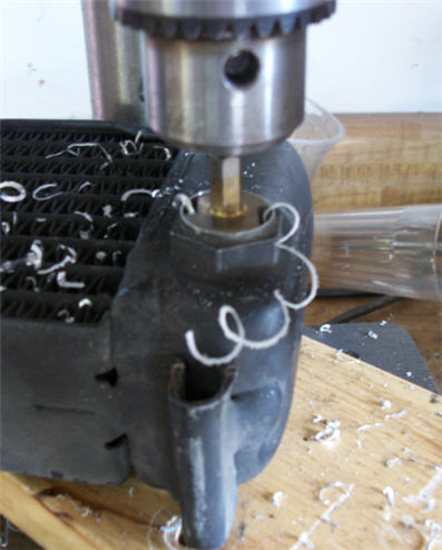
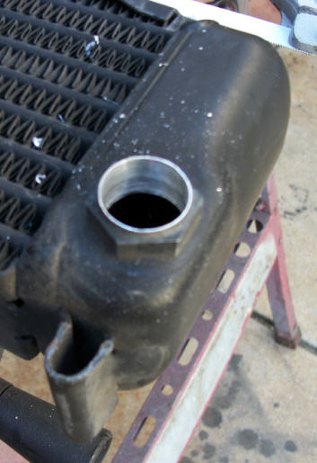
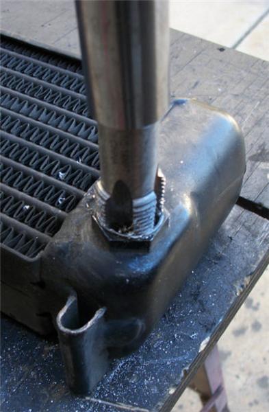
I'm pleased to report that it worked really well and provides another solution to oil line replacement for those that might want to go this route. It is a good match on size and there is plenty of metal on the cooler to support drilling and tapping. The first step is to cut off the threads.  The next step is to drill out the hole to 3/4". The closest size to the MB oil lines is AN -10 and the closest NPT to -10 is 1/2 that requires a 3/4" drill. There is a secret to this part of the process that will make life extremely easy - use a step drill that the largest size is 3/4". I've tried using a regular drill for 3/4" holes and it will bite and chatter and make a huge mess. The step drill goes through like butter.  Here's the hole ready for tapping.  Then just tap it and screw in your 1/2 NPT to -10 AN adapter. Make sure you keep the tap well oiled and back it out often to clear the threads. Never go with more torque than you've used in getting your fittings removed with galled thread. If in doubt put a wrench on the fitting on the cooler to take the load. I didn't feel I needed it as it never got really tight. Keep going until you get to a comfortable depth with your fittings. I wanted just a couple of threads showing when I was done.  Shown here is the adapter installed and a 90 degree -10 AN hose end (without a hose installed).  It's impossible to keep metal out of the cooler ends, so when you're done give them a really good cleaning. Any stray particles that you miss will get caught by the filter, so it might be a good idea to change the filter soon after doing this job. When I get the engine back in the car and the hoses measured and made up I'll post additional pictures.
__________________
Current Stable
Last edited by mach4; 01-30-2012 at 10:58 PM. Reason: Correct NPT fitting size |
 |
| Bookmarks |
|
|