I'd like to use this thread to tee up a discussion on the overall topic of electronic speedometer options for our vehicles.
I've run into the problem with my diesel conversion (617 into a 380SL) and
ROLLGUY is having a similar problem on his transmission swap of a 722.4 into a 300SD that originally came with an electronic speedo 722.3.
In both cases we thought that a tailcone swap would work but it is now painfully obvious that the two 722 transmissions (.3 vs .4) have different tailcones.
It is still possible that a tailcone from a C220 or a C280 will get the job done, but additional research points to that being a somewhat dubious proposition.
I'll explore some of the more exotic solutions in supplemental posts, but I'd like to set the stage for a discussion and additional options.
First, everything I can find points to the notion that the electronic speedometer pickup on the 722.3 and likely the 722.4 as well is a variable reluctance system consisting of a trigger wheel and a sensor.
Here is a picture of the internals of a 722.3 tailcone (from the 380SL) where the 4 "spoke" trigger wheel is clearly seen mounted to the parking pawl. The sensor reads each revolution through a voltage change from negative to positive.

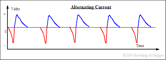
The wave form looks something like this
An in depth discussion of VR devices for triggering spark in Megasquirt using an EDIS device is here-
Distributor Pickups
Trigger wheels take many forms and the following image shows some of the kinds that have been used in ignition applications generally as part of a fuel injection system.

The first solution I'd like to toss out for discussion and critique is to create a "virtual trigger wheel" using the drive shaft as a base.
Here's a graphic of what I have in mind. The green are the "teeth" of the virtual trigger wheel, the purple is the stock MB sensor and the red is a custom bracket with appropriate adjustments for setting the clearance.

This proposed solution would use 4 carefully sized, fabricated and balanced steel "teeth" that would be epoxied to the drive shaft at exactly 90 degree intervals, as close to the front end as feasible. Taken in cross section we would have the equivalent of a 4 tooth trigger wheel, something like this.

It would not be prudent to rely on simple epoxy as a bonding agent, so I would use fiberglass, kevlar or carbon fiber cloth ribbon and epoxy to create a composite "band" around the driveshaft. Since these materials are quite light and would be evenly distributed, adverse balance effects should not be introduced. Rather than mount the sensor to the tunnel I would mount it to the rear transmission mount bracket to eliminate all but the tiniest and insignificant relative motion of the transmission and the driveshaft.
It seems as though this strategy would replicate the internal operation of the Mercedes system with an external "universal" alternative using the stock sensor, wiring and electronics which could be fabricated with relatively simple tools and materials.
Here's an article with a lot of great information on the subject of VSS (Vehicle Speed Sensors) -
VSS
Where am I wrong and what have I missed?